E-mail: email@fusonwindoor.com | Tel: +86-189-2593-0732

 English
 Views: 0 Author: Site Editor Publish Time: 2026-09-30 Origin: Site


Water eventually bypasses exterior window seals. You cannot build an absolutely impermeable facade. Wind-driven rain, thermal expansion, and sealant degradation guarantee moisture entry over the lifespan of any commercial or residential building. Relying solely on exterior caulking is a flawed strategy. You must engineer the extrusion to handle water intrusion predictably and safely.
Inadequate water management in an aluminum window frame leads to catastrophic envelope failures. Trapped moisture rots adjacent structural framing and breeds interior mold within wall cavities. Standing water degrades thermal breaks and compromises insulated glass unit (IGU) seals. These failures result in massive remediation costs and severe litigation risks for builders and architects. Evaluating drainage architectures allows you to specify fenestration meeting stringent structural demands. Different climate zones require specific water evacuation strategies. You must understand internal chamber geometries, pressure equalization, and gravity-fed pathways to protect the building envelope effectively.
Effective water management relies on pressure equalization, sloped internal geometries, and gravity-fed pathways rather than relying solely on exterior sealants.
Specifying a hidden drainage window offers superior architectural aesthetics but requires rigorous evaluation of maintenance accessibility and internal chamber design.
Performance validation must be based on standardized Water Penetration Resistance ratings (e.g., AAMA/WDMA/CSA 101/I.S.2/A440) specific to the project's wind-load and climate zone.
Long-term reliability hinges on correct sub-sill integration, proper setting block placement, and mitigation of installation tolerances during the construction phase.
Understanding how water breaches a building envelope requires analyzing the physical forces at play. Water does not simply fall onto a window; environmental forces drive it into the assembly. Defining these forces establishes the baseline criteria for successful mitigation. You must design systems that counteract kinetic energy, surface tension, and pressure differentials simultaneously.
Kinetic energy from wind drives rain horizontally against the glazing and frame. High-velocity winds push water droplets into microscopic gaps between the glass and the exterior gasket. A 50 mph wind exerts approximately 6.4 pounds per square foot (psf) of pressure against the facade. This pressure forces water through any defect in the exterior weather seal. Gravity pulls this surface water downward, concentrating the entire volume at the sill. When wind pressure meets gravity, water forces its way into the glazing pocket.
Capillary action complicates water management in tight joints. Surface tension draws water upward or inward through narrow gaps, defying gravity. If the clearance between the aluminum extrusion and the glass edge is less than 3mm, capillary forces will pull water upward over internal dams. Extrusion gaps must exceed specific dimensions—typically a minimum of 5mm—to break surface tension and allow water to flow freely downward. If drainage paths are improperly sized, capillary forces overcome gravity, and water infiltrates the interior.
Building HVAC systems and stack effects create negative interior building pressure. This negative pressure acts as a vacuum, drawing water through micro-fissures in the frame assembly. Even if gravity and capillary action are managed, negative pressure pulls standing water from the sill track directly into the wall cavity. Pressure equalization is mandatory to counteract this suction.
Contractors often rely on exterior caulking to keep water out. This approach fails. No exterior sealant lasts forever. UV exposure degrades EPDM and silicone glazing gaskets. Thermal expansion and contraction of the aluminum frame stretch and compress these seals daily. Over time, gaskets shrink, crack, and lose elasticity. Sealant joints fatigue and tear. Water entry into the extrusion is an inevitable reality.
Engineers apply the rainscreen or pressure-equalized design principle to window extrusions. Water entering the glazing pocket is an expected and managed design parameter. The exterior seal acts as a primary weather screen, deflecting the majority of the water. The internal glazing pocket acts as a secondary drainage plane. It catches the bypassed water and channels it safely back outside.
Pressure equalization involves venting the internal glazing pocket to the exterior. This equalizes the air pressure inside the frame with the wind pressure outside. When pressures equalize, the vacuum effect disappears. Water simply drops to the bottom of the glazing pocket via gravity. From there, internal channels route the moisture away from the interior envelope.
Engineers utilize different approaches to route water out of the extrusion. Comparing these architectures helps you select the right system for your specific project requirements. Each method balances aesthetics, manufacturing complexity, and environmental performance.
Face-drained systems utilize direct routing of water from the glazing pocket through the front face of the extrusion. Manufacturers punch or mill visible weep holes into the exterior face of the sill. Water drops into the sill track and flows horizontally out through these exposed holes. These holes typically measure 5mm by 20mm to ensure adequate flow volume.
This approach offers straightforward manufacturing. It requires less complex extrusion dies. Visual inspection is simple. Maintenance personnel easily spot blockages and clear debris from the weep holes using basic tools. The simplicity makes face-drained systems highly reliable in moderate climates with standard wind loads.
However, exposed weep holes create aesthetic disruption. They interrupt the clean lines of the aluminum profile. Unbaffled holes remain susceptible to wind-driven water blow-back. High winds push water back through the holes, flooding the sill. Additionally, high wind loads passing over open weep holes cause whistling and unwanted acoustic issues. Manufacturers often install plastic weep flaps to prevent blow-back, but these flaps become brittle and break off over time.
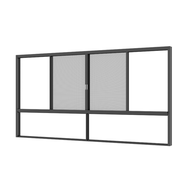
A hidden drainage window routes water vertically through the frame chambers. Water exits through the bottom of the sill, completely hidden from exterior view. The exterior face of the window remains smooth and uninterrupted by weep hole covers. This design relies on a complex network of internal baffles and vertical drop channels.
Concealed systems provide clean architectural lines. They significantly reduce the risk of direct wind-driven blow-back. The vertical routing creates a baffled pathway. Wind cannot easily push water upward against gravity through complex internal chambers. This makes hidden drainage superior for high-rise applications facing severe weather exposure and extreme dynamic wind loads.
The drawbacks involve complex internal extrusion profiles. The dies require intricate engineering, leading to higher manufacturing costs. Maintenance presents a challenge. If construction debris or organic matter clogs the internal chambers, clearing the blockage is difficult. You often cannot see the obstruction without disassembling the sash or removing the glazing bead.
The engineering of the glazing rebate and internal sill chambers must utilize gravity. Water cannot evacuate efficiently on a flat surface. A perfectly flat internal sill is a guaranteed failure point. Surface tension causes water to pool and stagnate. Stagnant water degrades the IGU edge seal, leading to premature glass fogging, and attacks the thermal break.
Extrusions require a minimum degree of slope to ensure rapid water evacuation. A sloped sill—typically engineered at a 5 to 7-degree angle—directs water immediately toward the weep holes or vertical drainage channels. This geometry prevents stagnant pooling. It ensures the glazing pocket dries quickly after a rain event, protecting the internal components from long-term moisture exposure.
A comprehensive aluminum window drainage system requires a secondary drainage plane beneath the primary window frame. Sub-sills act as continuous receptor channels. They catch any water that bypasses the primary frame drainage or leaks through the frame joinery at the mullion intersections.
Sub-sills are non-negotiable in commercial and multi-unit residential construction. They provide a continuous, watertight pan across the entire rough opening. They feature end dams to prevent water from spilling into the wall cavity at the jambs. The sub-sill directs all collected water outward, safely away from the building structure.
The window system must seamlessly interact with the building envelope's weather-resistive barrier (WRB). The sub-sill flashing must tie directly into the WRB. Proper shingle-lap integration ensures water shedding down the WRB flows over the sub-sill flashing, not behind it. Failure to integrate the sub-sill with the WRB renders the best window drainage useless.
Comparison of Drainage Architectures | ||
Feature | Face-Drained Systems | Hidden Drainage Systems |
|---|---|---|
Aesthetics | Visible weep holes/covers on exterior face | Clean, uninterrupted exterior profile |
Water Routing | Horizontal flow through the front face | Vertical flow through internal chambers |
Blow-Back Risk | High (if unbaffled) | Low (baffled by vertical design) |
Maintenance | Easy to inspect and clear | Difficult to access internal blockages |
Manufacturing Cost | Lower (simpler extrusion profiles) | Higher (complex internal dies) |
Translating technical features into verifiable performance outcomes requires understanding industry standards. You must specify quantifiable metrics to ensure the fenestration performs as required. Relying on marketing claims leads to envelope failures. Demand rigorous testing data from certified independent laboratories.
Design Pressure (DP) ratings and Performance Grades (PG) dictate window performance. These ratings evaluate structural load, air infiltration, and water resistance. The water penetration resistance is typically calculated as a percentage of the overall design wind load. Higher DP ratings indicate superior resistance to severe weather.
Testing methodology defines performance. ASTM E547 tests water penetration under cyclic static air pressure. ASTM E331 tests water penetration under uniform static air pressure difference. Dynamic testing, such as AAMA 501.1, involves wind generators driving water against the mock-up to simulate real-world storms. You must review these test reports carefully to ensure the system matches your site conditions.
Defining a waterproof aluminum window in a regulatory context means passing water resistance tests at specific pressures. Typically, a window must resist water infiltration at 15% to 20% of the design wind load. A window rated DP50 must withstand water testing at 7.5 to 10 psf without allowing water past the interior plane. This equates to resisting a 54 mph wind driving rain at 8 inches per hour.
Analyze the critical dimensions of weep holes. Holes must be large enough to break the surface tension of water. If a weep hole is too small, water bridges the gap and blocks the exit. Standard practice requires weep slots rather than round holes. Slots provide a wider exit path and handle larger volumes of water efficiently. A minimum of 50 square millimeters of open area per weep hole is standard practice.
Evaluate the role of weep flaps, baffles, and non-return valves. Severe storms push water against the building. Weep flaps act as one-way valves. They open to let water out but blow shut when wind hits them. Baffles inside the extrusion break the wind's kinetic energy, preventing reverse water flow into the sill track.
Manufacturing precision matters. Clean routing or punching of weep holes is mandatory. Field drilling often leaves metal burrs inside the chamber. These burrs catch construction dust, spider webs, and organic debris. Over time, this debris accumulates and completely blocks the water flow. Specify factory-punched weep slots with deburred edges to guarantee unobstructed drainage.
The critical relationship between glass setting blocks and drainage channels often dictates system success. Setting blocks support the heavy IGU. They transfer the glass weight to the aluminum frame. However, they sit directly in the sill track—the exact path water uses to reach the weep holes.
Specify the requirement for specialized, channeled setting blocks. Standard solid blocks act as dams. They block water flow, causing it to pool around the IGU edge seal. Channeled blocks feature grooves or elevated bridges. They support the glass while allowing water to flow freely underneath them toward the drainage exits. The material must be compatible with the IGU sealant, typically 85 Shore A durometer silicone or EPDM.
Positioning also impacts drainage. Installers place setting blocks at quarter points along the sill. If a weep hole aligns directly under a setting block, the drainage path is compromised. Engineering drawings must coordinate setting block locations with weep hole punching patterns to ensure unobstructed water evacuation.
Examine the intersection of thermal management and water management. Modern aluminum windows utilize polyamide struts or polyurethane pours to separate the interior and exterior metal profiles. These thermal breaks stop heat transfer. However, they sit inside the extrusion chambers where water flows.
Highlight the risk of water pooling on thermal breaks. Polyamide struts handle moisture well, but stagnant water degrades polyurethane pours over time. If drainage chambers lack proper slope, water sits on the thermal break. During freeze-thaw cycles, this trapped water expands, potentially fracturing the thermal barrier or the surrounding aluminum.
Engineers design drainage paths to route water away from the thermal break quickly. Sloped internal sills direct water toward the exterior chamber, keeping the thermal strut dry. Proper design ensures the thermal break remains structurally sound and thermally efficient throughout the window's lifespan.
Address the gap between factory testing and job-site realities. A window performs perfectly in a laboratory. That same window fails in the field if installed incorrectly. You must anticipate construction variables and implement strict mitigation strategies to protect the drainage architecture.
Plumb, level, and square deviations cause internal drainage slopes to fail. If an installer sets a window out of level, the engineered slope inside the sill track changes. Water flows away from the weep holes and pools in the corners. This standing water eventually overtops the internal dam and leaks inside.
Mitigate this risk by specifying adjustable installation brackets. Mandate strict shimming protocols. Installers must support the sill continuously to prevent bowing under the weight of the glass. Utilizing pan flashings with engineered back-dams provides a fail-safe. If the window leaks due to poor leveling, the pan flashing catches the water and directs it outward.
Perimeter sealing requires careful execution. Installers must seal the window frame to the rough opening without blocking the weep holes or the sub-sill drainage path. Over-caulking the exterior sill often traps water inside the wall cavity. Leave the bottom edge of the exterior trim unsealed to allow the sub-sill to drain freely.
Verify rough opening dimensions and substrate condition before installation.
Apply a continuous bead of compatible sealant along the sill plate.
Install the sub-sill pan flashing with a minimum 2-inch back dam.
Integrate the end dams with the vertical weather-resistive barrier.
Shim the sub-sill to ensure a positive slope toward the exterior.
Seal all fastener penetrations through the sub-sill immediately.
Construction dust, organic matter, or insect nesting blocks internal drainage paths. Drywall dust turns into a cement-like paste when wet. It clogs weep holes permanently. Pine needles and leaves accumulate in the sill track. Mud daubers build nests inside hidden drainage chambers. Blocked weeps void manufacturer warranties.
Design for maintainability. Specify removable glazing beads or snap-on sill covers. These features allow maintenance personnel to access the internal chambers and clean out debris. Hidden drainage systems require accessible clean-out ports. Without access, clearing a blockage requires destructive dismantling of the window sash.
Establish documented post-construction maintenance schedules. Building owners must clean sill tracks and inspect weep holes annually. Provide clear maintenance manuals to the facilities team. Documented maintenance protects warranty status and ensures the drainage system functions correctly for decades.
Freeze-thaw cycles present severe risks. If water traps inside the extrusion and freezes, it expands with immense force. This expansion fractures the aluminum extrusion. It breaks the glass edge seals, causing IGU failure. It shears the thermal break struts. Drainage paths must evacuate water rapidly before temperatures drop below freezing.
Coastal environments introduce saltwater corrosion. Saltwater entering the drainage chambers attacks the raw aluminum edges of punched weep holes. It degrades the thermal break connections. Specify anodized finishes or high-performance AAMA 2605 PVDF coatings on all internal hidden surfaces. These coatings protect the drainage chambers from aggressive coastal corrosion.
Framework for making safe specification decisions requires analyzing long-term value. Upfront compromises often lead to massive downstream liabilities. You must evaluate drainage systems based on total risk mitigation and structural performance.
Compare off-the-shelf commercial profiles with proprietary, highly engineered systems. Standard profiles utilize basic face-drained weep holes. They meet minimum code requirements. They offer lower DP ratings and struggle in severe weather environments. They rely heavily on perfect installation to function correctly.
Proprietary, pressure-equalized systems feature complex internal chambers and hidden drainage. They require expensive extrusion dies. However, they provide superior water resistance. They add architectural value to high-end projects by eliminating visible weep covers. They perform reliably in high-rise and coastal applications where wind loads are extreme.
Calculate the hidden impacts of water failure. When a poorly designed window leaks, the remediation efforts dwarf the initial material savings. You face exterior scaffolding setup, window removal, drywall replacement, and mold remediation. Tenant disruption causes severe operational issues. IGU seal failure requires complex glass replacement.
Position high-DP rated drainage systems as a risk-mitigation investment. A robust drainage architecture acts as an insurance policy for the building envelope. It protects the structural framing. It prevents interior damage. It eliminates litigation risks. The long-term performance justifies specifying advanced water management systems.
An aluminum window frame is only as durable as its internal drainage architecture. You must prioritize water management over simple aesthetics.
Match the drainage system type (face-drained vs. hidden) directly to the building's exposure category, height, and maintenance capabilities.
Request localized test reports (ASTM/AAMA) from manufacturers that align with your specific project design pressures.
Review extrusion cross-sections with a facade consultant to ensure proper sill slope and thermal break protection.
Specify channeled setting blocks in the glazing specifications to guarantee unobstructed water flow to the weep holes.
Mandate job-site mock-up testing (e.g., AAMA 502 or ASTM E1105) on the first installed units to verify installation tolerances before full-scale installation begins.
A: It works by capturing water that bypasses the exterior seals and routing it safely back outside. The system utilizes gravity, sloped internal sill chambers, and pressure equalization to direct water away from the insulated glass unit and out through engineered weep holes or hidden vertical channels.
A: A face-drained window routes water horizontally out through visible weep holes punched into the exterior front face of the sill. A hidden drainage window routes water vertically down through internal extrusion chambers, exiting at the bottom of the sill, leaving the exterior face smooth and uninterrupted.
A: No window is completely waterproof against all environmental forces forever. Exterior seals degrade over time. Instead of absolute impermeability, modern frames utilize pressure-equalized drainage systems to manage and evacuate the water that inevitably enters the glazing pocket.
A: Water pools when the drainage path is obstructed or the frame is installed out of level. Common causes include debris clogging the weep holes, solid setting blocks damming the water flow, or an improper installation that reverses the engineered slope of the internal sill.
A: You can clear face-drained weep holes using a stiff wire or compressed air to dislodge dirt and insects. For hidden drainage systems, you may need to remove the interior glazing beads or access specific clean-out ports to flush the internal vertical chambers with water.
A: It is a design that vents the internal glazing pocket to the exterior. This equalizes the air pressure inside the frame with the outside wind pressure. By eliminating the pressure differential, the system stops negative interior pressure from vacuuming water into the building envelope.


